Main points:2 players/teams Arduino based digital ScoreboardProgrammable using FTDI basic breakout boardAvailable in 3 sizes: 2.3″, 3″ and 4″ displaysWorks with SCORE4 module of Scoreduino appSend specific numbers to the displays using the appBluetoo
Secure Shopping
100% Safe Guarantee
Free Shipping
On orders over $30
Money-Back
30-Day Guarantee
Main points:
2 players/teams Arduino based digital Scoreboard
Programmable using FTDI basic breakout board
Available in 3 sizes: 2.3″, 3″ and 4″ displays
Works with SCORE4 module of Scoreduino app
Send specific numbers to the displays using the app
Bluetooth is the communication medium between the Scoreboard and app
Can be controlled with 4CH RF remote control
Use switches to manually increase or decrease the count
2.3″ scoreboards work with 9V and 3″ and 4″ scoreboards work with 12V.
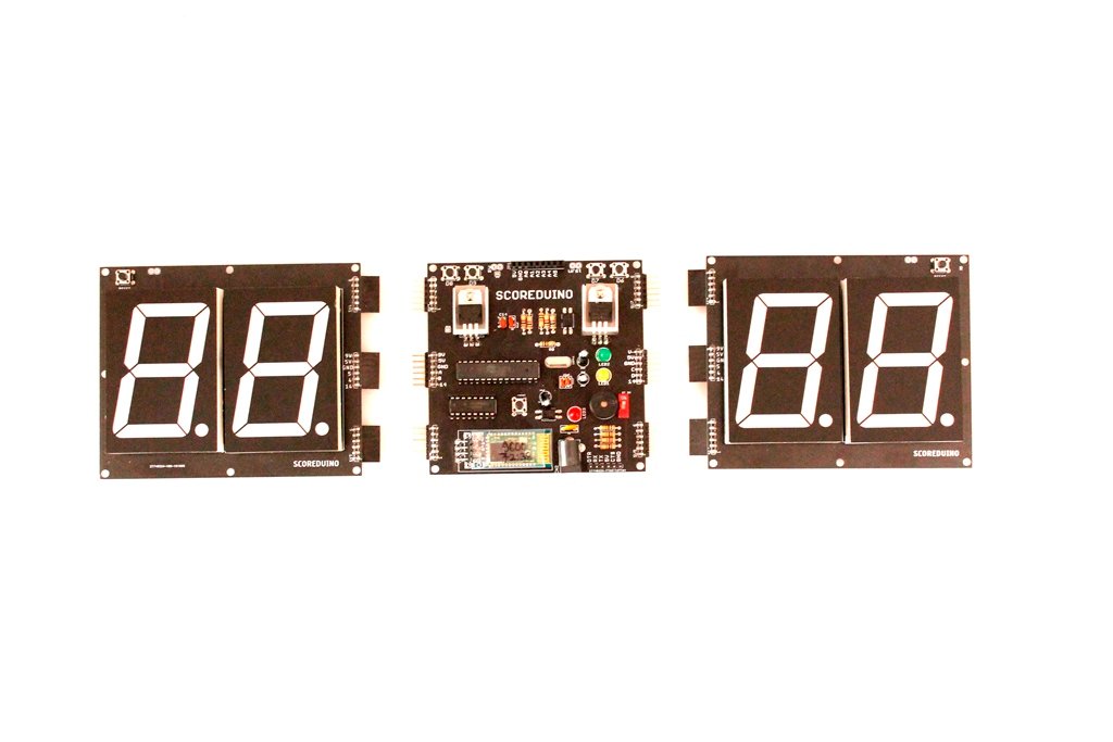
This is a DIY digital scoreboard for indoor games. All the modules of the scoreboard come fully assembled. You just have to find a way to fix it on a wooden board or make other arrangements.
There are 3 modules in each scoreboard:
SCOREDUINO-B: This is the central module of the Scoreboard. This is an Arduino-based controller supported by a Bluetooth module and an RF module for communicating with the 2 digits displays placed on its two sides. Read more about SCOREDUINO-B.
The right display: The right display gets up and down count commands from the central Scoreduino-B controller. The commands can be sent by RF remote control or SCORE4 module of the Scoreduino app. Specific numbers can also be sent to the right display.
The left display: The left display also gets up and down count commands from the central Scoreduino-B controller. The commands can be sent by RF remote control or SCORE4 module of the Scoreduino App. Specific numbers can also be sent to the left display.
Supporting modules:
RF receiver and the remote control: It uses the basic 4CH (the videos show 6CH, we sell 4CH only) RF module and remote control to send commands.
Bluetooth module: The scoreboard can be controlled with SCORE4 module of the Scoreduino App and it communicates via Bluetooth.
Power supplies:
2.3″ Scoreboard works with 9V. NOTE: We use LM7809 chip only for 2.3″ scoreboard.
3″ and 4″ Scoreboards work with 12V
How does it work?
To understand this working principle of Scoreboard, you need to understand two modules:
SCOREDUINO-B: This is an Arduino based controller that sends up and down commands to up and down counters. The schematic of SCOREDUINO-B.
Single-digit up and down counter module: We have described how 74LS192 based up and down counter modules work. You need to combine two of the single-digit counters and connect them to SCOREDUINO-B. The schematic of single-digit counter.
You can also read about Scoreduino-A.
These are the pins on the Scoreduino-B board:
On the left side:
9V: This is to power up RED colored 2.3″ displays. We get this voltage from the voltage regulator LM78XX.
5V: 5V is used for CD4511 and 74LS192/CD40192 on the left side
GND: GND of SCOREDUINO-B connects with the GND of 2 digits up/down counter
A: Send pulse from SCOREDUINO-B via this pin in order to count UP
B: Send pulse from SCOREDUINO-B via this pin in order to count down
14: Reset pin. Send pulse to reset the count.
On the right side:
V: V depends upon the color of the displays used on the right side. For example, GREEN colored 2.3″ display needs 12V. This is the default supply voltage.
5V: 5V is used for CD4511 and 74LS192/CD40192 on the right side
GND: GND of SCOREDUINO-B connects with the GND of 2 digits up/down counter
C: Send pulse from SCOREDUINO-B via this pin in order to count UP
D: Send pulse from SCOREDUINO-B via this pin in order to count down
![Worldwide Shipping Detachable Score4- Scoreduino-b Based Digital Scoreboard With 2.3″ Displays Flash Sale: 35% Off [vx83hCnf]](https://cdn.shopify.com/s/files/1/0217/9979/6836/files/DetachableSCORE4AndroidArduinoScoreboardScoreduino4digitsScoreboard_2.jpg?v=1711842234)


